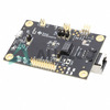
 DP83825EVMTexas InstrumentsDP83825EVM
 DP83822HRHBRTexas InstrumentsIC INTERFACE SPECIALIZED 32VQFN
 DP83822IFRHBTTexas InstrumentsIC INTERFACE SPECIALIZED 32VQFN
 DP83826ERHBRTexas InstrumentsLOW COST ENET PHY INDUSTRIAL
 DP83825IRMQRTexas InstrumentsIC TXRX FULL/HALF 1/1 24WQFN
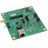 DP83822EVMTexas InstrumentsDP83822 10/100 MBPS ETHERNET PHY
 DP83822HFRHBTTexas InstrumentsIC INTERFACE SPECIALIZED 32VQFN
 DP83822IFRHBRTexas InstrumentsIC INTERFACE SPECIALIZED 32VQFN
 DP83826ERHBTTexas InstrumentsLOW COST ENET PHY INDUSTRIAL
 DP83822HFRHBRTexas InstrumentsIC INTERFACE SPECIALIZED 32VQFN
 DP83822IRHBRTexas InstrumentsIC INTERFACE SPECIALIZED 32VQFN
 DP83826EVMTexas InstrumentsDP83826 EVM
 DP83822IRHBTTexas InstrumentsIC INTERFACE SPECIALIZED 32VQFN
 DP83822IFRHBR/IFRHBTTexas Instruments
- Nath***rooks
- Jun 11, 2026

Image may be representation.
See specifications for product details.
See specifications for product details.
- EXPRESS OPTION
- Payment method
DP83822IRHB - Texas Instruments
- Manufacturer Part Number
- DP83822IRHB
- Manufacturer
- Texas Instruments
- Allelco Part Number
- 32D-DP83822IRHB
- Warranty
- 1 Year Allelco Warranty - Find out more
- Stock Status:
- 8,450 pcs available, New & Original
- Parts Description
- DAC91001
- Data sheet
- -
- Category
- Integrated Circuits (ICs) > Specialized ICs
- RoHs Status
- Our certification
- In stock: 8450


