View All

Please refer to the English Version as our Official Version.Return

Europe
France(Français) Germany(Deutsch) Italy(Italia) Russian(русский) Poland(polski) Czech(Čeština) Luxembourg(Lëtzebuergesch) Netherlands(Nederland) Iceland(íslenska) Hungarian(Magyarország) Spain(español) Portugal(Português) Turkey(Türk dili) Bulgaria(Български език) Ukraine(Україна) Greece(Ελλάδα) Israel(עִבְרִית) Sweden(Svenska) Finland(Svenska) Finland(Suomi) Romania(românesc) Moldova(românesc) Slovakia(Slovenská) Denmark(Dansk) Slovenia(Slovenija) Slovenia(Hrvatska) Croatia(Hrvatska) Serbia(Hrvatska) Montenegro(Hrvatska) Bosnia and Herzegovina(Hrvatska) Lithuania(lietuvių) Spain(Português) Switzerland(Deutsch) United Kingdom(English)
Asia/Pacific
Japan(日本語) Korea(한국의) Thailand(ภาษาไทย) Malaysia(Melayu) Singapore(Melayu) Vietnam(Tiếng Việt) Philippines(Pilipino)
Africa, India and Middle East
United Arab Emirates(العربية) Iran(فارسی) Tajikistan(فارسی) India(हिंदी) Madagascar(malaɡasʲ)
South America / Oceania
New Zealand(Maori) Brazil(Português) Angola(Português) Mozambique(Português)
North America
United States(English) Canada(English) Haiti(Ayiti) Mexico(español)
HomeProductsIntegrated Circuits (ICs)Embedded - MicrocontrollersSTM8AF52A9TAY
STM8AF52A9TAY Image
Image may be representation.
See specifications for product details.
EXPRESS OPTION
Payment method

STM8AF52A9TAY - STMicroelectronics

Manufacturer Part Number
STM8AF52A9TAY
Manufacturer
STMicroelectronics
Allelco Part Number
32D-STM8AF52A9TAY
Warranty
1 Year Allelco Warranty - Find out more
Stock Status:
12,382 pcs available, New & Original
Parts Description
IC MCU 8BIT 128KB FLASH 64LQFP
Package
64-LQFP (10x10)
Data sheet
STM8AF52A9TAY.pdf

PCN Packaging

2.73KHz.pdf

PCN Obsolescence/ EOL

Cylindrical Battery Holders.pdf

PCN Design/Specification

STM8AFx 07/Sep/2022.pdf
RoHs Status
ROHS3 Compliant
Our certification
In stock: 12382

Required fields are indicated by an asterisk (*)
Please send RFQ, we will respond immediately.

Quantity

Specifications

STM8AF52A9TAY Tech Specifications
STMicroelectronics - STM8AF52A9TAY technical specifications, attributes, parameters and parts with similar specifications to STMicroelectronics - STM8AF52A9TAY

Product Attribute Attribute Value
Manufacturer STMicroelectronics
Voltage - Supply (Vcc/Vdd) 3V ~ 5.5V
Supplier Device Package 64-LQFP (10x10)
Speed 24MHz
Series STM8A
RAM Size 6K x 8
Program Memory Type FLASH
Program Memory Size 128KB (128K x 8)
Peripherals Brown-out Detect/Reset, POR, PWM, WDT
Package / Case 64-LQFP
Package Tray
Product Attribute Attribute Value
Oscillator Type Internal
Operating Temperature -40°C ~ 85°C (TA)
Number of I/O 52
Mounting Type Surface Mount
EEPROM Size 2K x 8
Data Converters A/D 16x10b
Core Size 8-Bit
Core Processor STM8A
Connectivity CANbus, I²C, LINbus, SPI, UART/USART
Base Product Number STM8

Environmental & Export Classifications

ATTRIBUTE DESCRIPTION
RoHs Status ROHS3 Compliant
Moisture Sensitivity Level (MSL) 3 (168 Hours)
REACH Status REACH Unaffected
ECCN EAR99
HTSUS 8542.31.0001

Parts Introduction

STM8AF52A9TAY Image
STM8AF52A9TAY (1)

Manufacturer Part Number

STM8AF52A9TAY

Manufacturer

stmicroelectronics

Introduction

The STM8AF52A9TAY is a high-performance 8-bit microcontroller from stmicroelectronics, designed for automotive and industrial applications.

Product Features and Performance

Core Processor: STM8A

Core Size: 8-Bit

Speed: 24MHz

Connectivity: CANbus, I2C, LINbus, SPI, UART/USART

Peripherals: Brown-out Detect/Reset, POR, PWM, WDT
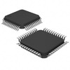
Number of I/O: 52

Program Memory Size: 128KB

Program Memory Type: FLASH

EEPROM Size: 2K x 8

RAM Size: 6K x 8

Voltage Supply: 3V to 5.5V

Data Converters: A/D 16x10b

Oscillator Type: Internal

Operating Temperature: -40°C to 85°C

Product Advantages

Extensive connectivity options

High number of I/O ports for versatile interfacing

Robust peripheral set supporting advanced control

Key Technical Parameters

Speed: 24MHz

EEPROM Size: 2K x 8

RAM Size: 6K x 8

Program Memory: 128KB FLASH

A/D Converters: 16x10b

Operating Voltage: 3V to 5.5V

Temperature range: -40°C to 85°C

Quality and Safety Features

Brown-out Detect/Reset

Power-on Reset (POR)

Watchdog Timer (WDT)

Compatibility

Compatible with STM8A series toolset and development environment

Application Areas

Automotive control systems

Industrial automation

Embedded systems design

Product Lifecycle

Status: Not For New Designs

Replacements and upgrades may be limited; check for available newer models in the STM8A series

Several Key Reasons to Choose This Product

Robust temperature and voltage range suitable for harsh environments

Rich connectivity features allowing for comprehensive system integration

Adequate memory options ensuring sufficient data storage and processing capacity

Comprehensive set of peripherals enhancing component functionality and reliability

Extended support and compatibility with existing STM8A family products

Frequently Asked Questions(FAQ)

What is the maximum operating frequency and corresponding power consumption trade-off when using the STM8AF52A9TAY microcontroller at 3.3V versus 5V supply voltage?
The STM8AF52A9TAY operates at a nominal maximum frequency of 24MHz across its entire voltage range of 3V to 5.5V. At 3.3V, typical current consumption during active execution of code from flash is approximately 1.2mA/MHz, resulting in about 28.8mA at full speed. At 5V, due to higher internal switching voltages, current increases to roughly 1.6mA/MHz, or about 38.4mA at 24MHz. This implies a power increase of nearly 33% when operating at 5V without any clock scaling. Engineers must balance noise margin, I/O drive strength, and thermal constraints when selecting the supply voltage for battery-powered or high-noise environments.
How does the STM8AF52A9TAY compare to the STM8AF52A6TAY in terms of program memory and peripheral availability, and which would be more suitable for a CANbus application requiring 128KB flash?
The STM8AF52A9TAY features 128KB of embedded flash memory and includes full CANbus support, while the STM8AF52A6TAY offers only 32KB of flash and lacks CANbus functionality. Both share identical core architecture, speed (24MHz), and package (64-LQFP), but the A9 variant supports larger firmware applications and real-time industrial communication protocols. For a CANbus design requiring substantial program space—such as implementing complex protocol stacks or bootloaders—the STM8AF52A9TAY is the only viable option among these two part numbers.
What are the key differences between using the internal RC oscillator versus an external crystal with the STM8AF52A9TAY, particularly regarding timing accuracy and startup time in automotive-grade systems?
The STM8AF52A9TAY provides multiple internal clock sources including a 16MHz HSI RC oscillator (±2% accuracy over temperature) and a 131kHz LSE for low-power timing. Using an external crystal improves frequency accuracy to ±20ppm but adds cost, board space, and longer startup time due to PLL lock cycles. In safety-critical or precision-timed applications like motor control or sensor sampling, external crystals reduce jitter and improve ADC timing stability. However, for simple UART baud rate generation or non-time-sensitive tasks, the internal oscillator suffices and reduces BOM complexity.
Can the STM8AF52A9TAY reliably operate in industrial temperature ranges (-40°C to +85°C) when driving capacitive loads on its GPIO pins, and what precautions should be taken?
Yes, the STM8AF52A9TAY is qualified for -40°C to +85°C operation per its datasheet specifications. However, driving capacitive loads beyond 10–15pF per pin may degrade rise/fall times and increase power consumption, potentially causing signal integrity issues at 24MHz system clocks. To maintain reliable operation, use series termination resistors (e.g., 22–100Ω) near high-speed lines and ensure adequate decoupling capacitance (typically 100nF ceramic + 10µF bulk) close to VDD pins. Avoid long traces and minimize fanout where possible.
What is the effective data retention period for the EEPROM emulation layer if the STM8AF52A9TAY undergoes frequent write cycles in a logging application?
The STM8AF52A9TAY embeds 2KB of user-accessible EEPROM memory, which supports up to 100,000 write/erase cycles per location under normal conditions. In a typical logging scenario writing once per minute, this equates to over 17 years of continuous operation. However, wear-leveling algorithms implemented in firmware are essential to distribute writes evenly across logical sectors, preventing premature failure. Without such management, localized degradation could occur within months, especially if certain addresses are written repeatedly.
How many analog input channels can be simultaneously sampled by the STM8AF52A9TAY’s 10-bit ADC, and what factors influence conversion accuracy in noisy environments?
The STM8AF52A9TAY integrates a 16-channel, 10-bit successive approximation ADC capable of single-ended measurements. Simultaneous sampling is not supported; however, fast channel switching allows effective multi-channel acquisition. Conversion accuracy depends on reference stability, input impedance matching, and noise filtering. For best results, use a 2.5V internal bandgap reference, disable unused peripherals during conversion, and apply software averaging (e.g., 4–8 samples) to suppress transient interference. External RC filters on inputs (>10kΩ + 100nF) further improve SNR in industrial settings.
Is it feasible to implement hardware-based watchdog functionality with windowed supervision using the STM8AF52A9TAY, and how does this affect system reliability in unattended operations?
Yes, the STM8AF52A9TAY includes an independent watchdog timer (IWDG) that can be configured for either free-running or windowed mode via firmware. Windowed supervision requires precise timing calibration and adds complexity but prevents both runaway code and early resets. When enabled, the IWDG forces a reset if not refreshed within a defined interval, enhancing fault tolerance in battery-operated or remote monitoring systems. Pairing this with the main WDG peripheral enables layered recovery strategies, significantly improving mean time between failures (MTBF) in field-deployed devices.
What considerations apply when interfacing the STM8AF52A9TAY with LINbus networks, and how does its built-in LIN transceiver simplify compliance testing?
The STM8AF52A9TAY includes a dedicated LIN transceiver interface supporting ISO 9141-2 and SAE J2602 standards. This eliminates the need for discrete transceivers like TJA1020, reducing component count and PCB area. Key design considerations include proper termination (typically 1kΩ pull-up to battery), bus slew rate control, and isolation if communicating with high-voltage subsystems. Firmware must handle wake-up patterns, checksum validation, and fault detection per LIN specification v2.1/v2.2. Compliance with automotive EMC requirements often necessitates layout symmetry and ground plane segmentation to minimize radiated emissions.
How does the choice between SPI and I2C affect throughput and pin usage when connecting multiple sensors to the STM8AF52A9TAY in a compact 64-pin design?
SPI typically delivers higher throughput (up to ~2Mbps with 24MHz clock) and simpler master-only control, ideal for high-speed sensors like ADCs or displays. However, it consumes one additional chip select (CS) line per device, increasing pin utilization. I2C uses only two shared lines (SDA/SCL) regardless of device count, saving pins but limited to ~400kHz (standard mode) or 3.4MHz (fast mode). With only 52 available GPIOs, minimizing pin overhead favors I2C for moderate-speed peripherals (e.g., temperature sensors, EEPROMs). For the STM8AF52A9TAY, careful routing and pull-up resistor selection become critical in dense layouts to avoid bus contention.
What are the implications of using flash memory as general-purpose RAM in the STM8AF52A9TAY, and when might this approach be beneficial?
The STM8AF52A9TAY’s 128KB flash allows flexible memory mapping, enabling execution from RAM-like regions via XRAM addressing. This technique reduces latency for frequently accessed variables compared to flash reads, which have ~2x slower access times. While convenient for prototyping, repeated execution from flash can increase power consumption and reduce endurance. Use cases include real-time control loops or interrupt service routines where deterministic timing outweighs power savings. Always validate performance gains against cache simulation tools and consider relocating critical functions to the 6KB of true RAM for optimal efficiency.
Does the STM8AF52A9TAY support low-power modes compatible with wake-on-interrupt from peripheral modules, and what is the typical current draw in stop mode?
Yes, the STM8AF52A9TAY offers multiple low-power modes, including Wait (WFI), Active-Halt, and Stop modes. In Stop mode with clock disabled and all peripherals off, current drops to ~1.5µA at 3.3V. Wake-up can occur via external interrupts, RTC alarms, comparator events, or LIN/UART wake signals. Transition latency from Stop to active state is typically 1–2ms, depending on oscillator restart time. This makes the STM8AF52A9TAY suitable for energy-harvesting IoT nodes requiring weeks of operation from a single coin cell.
How should developers manage stack overflow risks when compiling large applications for the STM8AF52A9TAY, given its modest RAM size?
With only 6KB of RAM, the STM8AF52A9TAY demands careful memory discipline. Stack growth must be bounded by static analysis tools or linker scripts defining strict heap/stack partitions. Embedded IDEs like Cosmic or ST Visual Develop allow setting minimum stack sizes based on worst-case call depth. Recursive algorithms or deeply nested ISRs should be avoided. Monitoring SP (stack pointer) during debug sessions helps detect overruns early. For applications exceeding 4KB of local variables or deep function calls, refactoring into smaller modules or using static allocation is strongly advised.
What role does brown-out detection play in protecting firmware integrity on the STM8AF52A9TAY during voltage sags, and how is it configured?
The STM8AF52A9TAY includes an integrated brown-out detector (BOD) that triggers a reset when VDD falls below programmable thresholds (2.4V, 2.7V, or 3.0V). This prevents erratic behavior caused by undervoltage conditions, such as corrupted flash writes or register corruption. The BOD remains active even in low-power modes, ensuring robust operation in unstable power environments. Configuration is done via option bytes, allowing customization based on application needs—critical in automotive or solar-powered systems where voltage dips are common.
Can the PWM module on the STM8AF52A9TAY generate complementary outputs for motor control, and what resolution can be achieved?
Yes, the STM8AF52A9TAY features advanced-control timers (TIM1 and TIM4) capable of generating center-aligned or edge-aligned PWM waveforms with dead-time insertion for half-bridge or H-bridge motor drivers. Using TIM1’s 16-bit counter, resolution reaches 152.6µs at 24MHz (1/24M ≈ 41.7ns), enabling fine duty-cycle control down to ~0.4%. Complementary pairs with programmable dead time (up to 16µs in 100ns steps) enhance safety in brushed DC motor applications. Firmware must configure capture/compare registers and enable complementary output mode via CCxE bits.
What precautions are necessary when updating firmware via UART bootloader on the STM8AF52A9TAY to prevent bricking the device?
Firmware updates require reliable handshake protocols, checksum verification (e.g., CRC-16), and atomic write sequences to avoid partial programming. The STM8AF52A9TAY supports in-system programming (ISP) through UART, but interruption during flash erase/write cycles can corrupt the boot block. Implement dual-bank flash or backup image storage if possible. Also, ensure stable power during update and use a robust baud rate negotiation mechanism. Never disable the WDG or BOR during flashing—these safeguards must remain active until the new image is fully verified.
How does the STM8AF52A9TAY’s Moisture Sensitivity Level (MSL) of 3 affect storage and handling before assembly in high-volume manufacturing?
Rated MSL 3 (168 hours), the STM8AF52A9TAY must be assembled within one week after opening moisture-barrier bags if not baked. Exposure beyond this window risks delamination during solder reflow due to steam formation. Facilities must follow JEDEC J-STD-033 guidelines: store parts in dry cabinets (<10% RH) and bake at 125°C for 24 hours if threshold exceeded. Proper labeling and FIFO rotation prevent accidental use of compromised components. This is especially critical in lead-free reflow profiles exceeding 240°C peak temperature.

Parts with Similar Specifications

The three parts on the right have similar specifications to STMicroelectronics STM8AF52A9TAY

Product Attribute STM8AF52A9TCY STM8AF52A8TAY STM8AF52AATAY STM8AF52AATAX
Part Number STM8AF52A9TCY STM8AF52A8TAY STM8AF52AATAY STM8AF52AATAX
Manufacturer STMicroelectronics STMicroelectronics STMicroelectronics STMicroelectronics
Package / Case - 196-LFBGA 16-DIP (0.300', 7.62mm) 64-VFQFN Exposed Pad
Data Converters - - - -
Oscillator Type - - - -
Package - Tape & Reel (TR) Tube Tape & Reel (TR)
Series - - - -
Speed - - - -
Connectivity - - - -
Operating Temperature - -40°C ~ 85°C 0°C ~ 70°C -40°C ~ 85°C
Voltage - Supply (Vcc/Vdd) - - - -
Number of I/O - - - -
Program Memory Type - - - -
EEPROM Size - - - -
Peripherals - - - -
Supplier Device Package - 196-NFBGA (12x12) 16-PDIP 64-VQFN (9x9)
Core Processor - - - -
Base Product Number - DAC34H84 MAX500 ADS62P42
Core Size - - - -
Program Memory Size - - - -
RAM Size - - - -
Mounting Type - Surface Mount Through Hole Surface Mount

STM8AF52A9TAY Datasheet PDF

Download STM8AF52A9TAY pdf datasheets and STMicroelectronics documentation for STM8AF52A9TAY - STMicroelectronics.

HTML Datasheet
STM8AF52xx, STM8AF62xx.pdf
PCN Packaging
2.73KHz.pdf
PCN Obsolescence/ EOL
Cylindrical Battery Holders.pdf
PCN Assembly/Origin
STM8A Testing Chgs 13/Dec/2021.pdf
PCN Design/Specification
STM8AFx 07/Sep/2022.pdf

Customer Reviews

Evaluation: 10 Articles

  • Nath***rooks
    Jun 11, 2026

    Installed this power component in a converter board. Output remained stable under different load conditions and thermal performance was better than expected.

  • Dani***alkerTech
    Jun 1, 2026

    Product works, but setup took more effort than expected. Once configured the MCU ran reliably, although documentation support felt older compared with newer platforms. Fine for maintenance projects.

  • Yuki***aka88
    May 26, 2026

    信号通信プロジェクトでこのRS-485トランシーバーを使用しました。設置は簡単で、長距離ケーブルでも通信は安定していました。消費電力も、以前使用していたものより低くなっています。

  • Stev***aker
    May 20, 2026

    Solid diode for power rectification. Works well in switching circuits.

  • Bran***Lewis
    May 11, 2026

    Compact FPGA with good performance. Suitable for basic signal processing tasks.

  • Oliv***arris
    May 7, 2026

    Reliable I/O expander. Works well in embedded control applications.

  • Jess***Jones
    Apr 17, 2026

    It offers good value for the price, and the specifications match the description. I’ve been using it for two days with no issues, and I’ll definitely buy it again if I need it in the future.

  • Mich***Smith
    Apr 17, 2026

    Shipping was on time, the component pins are neatly aligned, and I tested 10 of them with a multimeter—all readings were within the specified range. Highly recommended.

  • Aman***arris
    Apr 3, 2026

    It was great—the entire process, from placing the order to receiving the package, went very smoothly. The components were consistent, the price was fair, and I had a very pleasant shopping experience.

  • Mike***nch
    Apr 3, 2026

    Better than expected! The resistance and capacitance readings were spot-on, and it passed the test on the first try. The service was reliable, and the packaging was thoughtful—I highly recommend it.

Write a Review

Your Email address will not be published.

Shipment

Delivery Time

In-stock items can be shipped within 24 hours. Some parts will be arranged for delivery within 1-2 days from the date all items arrive at our warehouse. And Allelco ships order once a day at about 17:00, except Sunday. Once the goods are shipped, the estimated delivery time depends on the shipping methods and Delivery destination. The table below shows are the logistic time for some common countries.

Delivery Cost

  1. Use your express account for shipment if you have one.
  2. Use our account for the shipment. Refer to the table below for the approximate charges.
(Different time frame / countries / package size has different price.)

Delivery Method

  1. Global Common Shipment by DHL / UPS / FedEx / TNT / EMS / SF we support.
  2. Others more shipping ways, please get in touch with your customer manager.

Common Countries Logistic Time Reference
Region Country Logistic Time(Day)
America United States 5
Brazil 7
Europe Germany 5
United Kingdom 4
Italy 5
Oceania Australia 6
New Zealand 5
Asia India 4
Japan 4
Middle East Israel 6
DHL & FedEx Shipment Charges Reference
Shipment charges(KG) Reference DHL(USD$)
0.00kg-1.00kg USD$30.00 - USD$60.00
1.00kg-2.00kg USD$40.00 - USD$80.00
2.00kg-3.00kg USD$50.00 - USD$100.00
Note:
The above table is for reference only. There may have some data bias for the uncontrollable factors.
Contact us if you have any questions.
  • QC (Quality Warranty)
  • Payment Support
  • Packaging
  • Certifications & Memberships

QC (Quality Warranty)

Allelco is committed to exceeding customer expectations through customer service excellence, order accuracy, and on-time delivery.
This is achieved through our commitment to the continual improvement of our processes, services, and products.


Strict quality inspection builds a solid foundation for electronic component quality.
  1. Visual inspection
  2. Performance testing and reliability verification
  3. Standardized full-process testing
  4. Precise control of every parameter
We eliminate defective components and ensure the stable operation of electronic devices through professional quality standards.

Payment Support

The payment method can be chosen from the methods shown below: Wire Transfer (T/T, Bank Transfer), Western Union, Credit card, PayPal.
  • HKBea
  • Paypal
  • MasterCard
  • Western-Union
  • VISA
Stable Delivery, Sincere Partnership — Your Faithful Supply Chain Partner
  • Efficient Supply Management
  • Cost-Saving Procurement
  • Fast Sourcing & Delivery
Contact us if you have any questions.

Packaging

Electrostatic Discharge Protection and Handling

All electrostatic-sensitive components are handled in accordance with electrostatic discharge control procedures. The products are hermetically sealed in anti-static safe packaging to prevent electrostatic damage. Appropriate labeling is also applied for identification and traceability. This ensures product integrity during storage, handling and transportation.


ESD

Certifications & Memberships

Third-party certified, strict quality control. Our certification
  • ISO 9001: 2015
  • ISO 13485: 2016
  • ISO 14001: 2015
  • ISO 28000: 2007
  • ISO 45001: 2018
  • GB/T 27922-2011
  • SMTA
  • IPC
  • ESD
  • PSMA
STM8AF52A9TAY Image

STM8AF52A9TAY

STMicroelectronics
32D-STM8AF52A9TAY

Want a better price? Add to Cart and Submit RFQ now, we'll contact you immediately.

0 RFQ
Shopping cart (0 Items)
It is empty.
Compare List (0 Items)
It is empty.
Feedback

Your feedback matters! At Allelco, we value the user experience and strive to improve it constantly.
Please share your comments with us via our feedback form, and we'll respond promptly.
Thank you for choosing Allelco.

Subject
E-mail
Comments
Captcha
Drag or click to upload file
Upload File
types: .xls, .xlsx, .doc, .docx, .jpg, .png and .pdf.
Max file size: 10MB