View All

Please refer to the English Version as our Official Version.Return

Europe
France(Français) Germany(Deutsch) Italy(Italia) Russian(русский) Poland(polski) Czech(Čeština) Luxembourg(Lëtzebuergesch) Netherlands(Nederland) Iceland(íslenska) Hungarian(Magyarország) Spain(español) Portugal(Português) Turkey(Türk dili) Bulgaria(Български език) Ukraine(Україна) Greece(Ελλάδα) Israel(עִבְרִית) Sweden(Svenska) Finland(Svenska) Finland(Suomi) Romania(românesc) Moldova(românesc) Slovakia(Slovenská) Denmark(Dansk) Slovenia(Slovenija) Slovenia(Hrvatska) Croatia(Hrvatska) Serbia(Hrvatska) Montenegro(Hrvatska) Bosnia and Herzegovina(Hrvatska) Lithuania(lietuvių) Spain(Português) Switzerland(Deutsch) United Kingdom(English)
Asia/Pacific
Japan(日本語) Korea(한국의) Thailand(ภาษาไทย) Malaysia(Melayu) Singapore(Melayu) Vietnam(Tiếng Việt) Philippines(Pilipino)
Africa, India and Middle East
United Arab Emirates(العربية) Iran(فارسی) Tajikistan(فارسی) India(हिंदी) Madagascar(malaɡasʲ)
South America / Oceania
New Zealand(Maori) Brazil(Português) Angola(Português) Mozambique(Português)
North America
United States(English) Canada(English) Haiti(Ayiti) Mexico(español)
HomeProductsIntegrated Circuits (ICs)Interface - I/O ExpandersPCA9555HF,118
PCA9555HF,118 Image
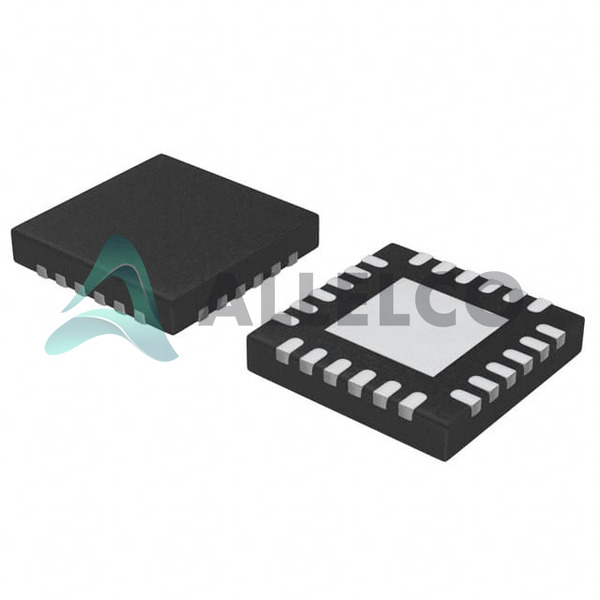
Image may be representation.
See specifications for product details.
EXPRESS OPTION
Payment method

PCA9555HF,118 - NXP USA Inc.

Manufacturer Part Number
PCA9555HF,118
Manufacturer
NXP Semiconductors
Allelco Part Number
98D-PCA9555HF,118
Warranty
1 Year Allelco Warranty - Find out more
Stock Status:
8,942 pcs available, New & Original
Parts Description
IC XPND 400KHZ I2C SMBUS 24HWQFN
Package
24-HWQFN (4x4)
Data sheet
PCA9555HF,118.pdf
RoHs Status
ROHS3 Compliant
Our certification
In stock: 8942

Required fields are indicated by an asterisk (*)
Please send RFQ, we will respond immediately.

Quantity

Specifications

PCA9555HF,118 Tech Specifications
NXP USA Inc. - PCA9555HF,118 technical specifications, attributes, parameters and parts with similar specifications to NXP USA Inc. - PCA9555HF,118

Product Attribute Attribute Value
Manufacturer NXP Semiconductors
Voltage - Supply 2.3V ~ 5.5V
Supplier Device Package 24-HWQFN (4x4)
Series -
Package / Case 24-WFQFN Exposed Pad
Package Tape & Reel (TR)
Output Type Push-Pull
Operating Temperature -40°C ~ 85°C
Product Attribute Attribute Value
Number of I/O 16
Mounting Type Surface Mount
Interrupt Output Yes
Interface I²C, SMBus
Features POR
Current - Output Source/Sink 10mA, 25mA
Clock Frequency 400 kHz
Base Product Number PCA95

Environmental & Export Classifications

ATTRIBUTE DESCRIPTION
RoHs Status ROHS3 Compliant
Moisture Sensitivity Level (MSL) 1 (Unlimited)
REACH Status REACH Unaffected
ECCN EAR99
HTSUS 8542.39.0001

Frequently Asked Questions(FAQ)

What are the key differences between the PCA9555HF,118 and PCA9555AHF,128 in terms of electrical characteristics and thermal performance for high-density PCB designs?
The PCA9555HF,118 features a 400 kHz I²C/SMBus interface and operates across a supply voltage range of 2.3 V to 5.5 V with a maximum operating temperature of 85°C. While both variants share similar core functionality—such as 16 bidirectional I/Os, push-pull outputs capable of sourcing up to 25 mA and sinking up to 10 mA, and an integrated power-on reset (POR) circuit—the PCA9555AHF,128 is specified over a broader industrial temperature range (-40°C to +125°C), making it more suitable for harsh environments. The HF suffix typically denotes a lead-free, RoHS3-compliant package variant, which may influence solder reflow profiles and thermal cycling reliability in mass production. Designers should evaluate not only the extended temperature rating but also any variations in leakage current or input threshold levels when substituting between these two part numbers.
How does the interrupt output feature of the PCA9555HF,118 function in real-world applications, and what considerations are necessary to ensure reliable edge detection during system operation?
The PCA9555HF,118 provides an active-low interrupt output that asserts when any change occurs on its 16 GPIO lines, provided global interrupt enable bits are set. This mechanism reduces CPU polling overhead by signaling asynchronous events such as button presses or sensor state changes. To ensure robust operation, the host microcontroller must implement proper debouncing logic in firmware, especially when interfacing mechanical switches, since the internal Schmitt-trigger inputs can still respond to noise unless filtered externally. Additionally, care must be taken to avoid false triggers during power-up transients due to the device’s POR circuitry, which resets all registers and disables interrupts until stable supply conditions are met—typically within 10 ms after VCC reaches 2.3 V.
Can the PCA9555HF,118 safely drive inductive loads like relays or solenoids directly from its GPIO outputs without additional buffering components?
No, the PCA9555HF,118 is not designed to directly drive inductive loads such as relays or solenoids. Each I/O pin can source up to 25 mA and sink up to 10 mA, but inductive kickback can generate voltage spikes exceeding the 5.5 V absolute maximum rating if no flyback diode is used. In practice, driving such loads requires external MOSFETs or transistor drivers. For example, switching a 5 V relay coil rated at 70 mA would exceed the PCA9555HF,118’s per-pin current capability and risk damaging the IC. Therefore, designers must use discrete switching elements or dedicated load drivers when implementing relay control through this expander.
What impact does clock stretching have on communication stability when using the PCA9555HF,118 with a slow master processor?
Clock stretching is fully supported by the PCA9555HF,118 via its SMBus compliance, allowing the slave device to delay data transfer by holding the SCL line low. This is particularly useful when interfacing with slow microcontrollers or peripherals that require extra time to process register writes. However, excessive or unpredictable clock stretching can introduce latency and complicate timing budgets in time-critical systems. Designers should ensure their I²C master accommodates variable wait states and avoids timeouts during configuration phases. In most applications, clock stretching adds negligible overhead unless multiple bytes are transferred consecutively, where cumulative delay may become noticeable.
How does the PCA9555HF,118 compare to the TCA9535RTWR in terms of input hysteresis and noise immunity for noisy industrial environments?
Both the PCA9555HF,118 and TCA9535RTWR offer 16-bit I/O expanders with I²C interfaces, but the PCA9555HF,118 includes built-in Schmitt-trigger inputs, providing superior noise immunity compared to standard CMOS logic. While exact threshold specifications vary slightly between vendors, NXP’s implementation typically offers higher hysteresis than TI’s TCA9535RTWR, making it less susceptible to glitches near logic transition points. This characteristic makes the PCA9555HF,118 preferable in electrically noisy settings such as motor control panels or factory automation, where EMI from nearby power lines could otherwise corrupt input readings. Nevertheless, both devices benefit from external filtering capacitors when used with long trace lengths.
What precautions should be taken during PCB layout to minimize signal integrity issues when routing SDA and SCL lines connected to the PCA9555HF,118?
To maintain reliable I²C communication with the PCA9555HF,118, keep SDA and SCL traces as short as possible and route them parallel to each other with consistent spacing to reduce crosstalk. Terminate these lines with pull-up resistors (typically 2.2 kΩ to 10 kΩ) close to the bus master, ensuring they comply with the 400 kHz fast-mode timing requirements. Avoid vias under the 24-HWQFN package unless absolutely necessary, as parasitic inductance can degrade rise/fall times. Also, place decoupling capacitors—100 nF ceramic—as close as possible to the VCC and GND pins of the PCA9555HF,118 to suppress supply transients during switching activity.
Is it feasible to cascade multiple PCA9555HF,118 devices on the same I²C bus, and what addressing limitations apply?
Yes, multiple PCA9555HF,118 devices can be cascaded on a single I²C bus, but each unit occupies one of four possible 7-bit slave addresses (0x40–0x43). These addresses are determined by the logic state of the A0, A1, and A2 input pins, which must be tied to VDD, GND, or left floating accordingly. Since the base address is fixed at 0x20 shifted left by one bit, only four unique addresses are available per bank. If more than four expanders are needed, designers must either use different I²C buses, implement software-based multiplexing, or select alternative parts with configurable secondary addressing schemes.
What role does the Power-On Reset (POR) circuit play in the initialization sequence of the PCA9555HF,118, and how long does it take to stabilize?
The POR circuit within the PCA9555HF,118 ensures all internal registers default to known states upon power-up, preventing undefined behavior during boot sequences. It activates once the supply voltage exceeds approximately 1.2 V and remains asserted until VCC stabilizes above the functional threshold (~2.3 V). During this period, the interrupt output stays inactive, and register access attempts are ignored. Based on typical ramp rates, full stabilization occurs within 10–20 ms after reaching nominal voltage, aligning with the device’s specified operating conditions. Firmware should therefore delay GPIO configuration until after confirming stable power delivery.
How do the output drive strengths of the PCA9555HF,118 compare to those of the MAX7312ATG+T, and which is better suited for driving LEDs with varying brightness requirements?
The PCA9555HF,118 delivers up to 25 mA sink current per pin, sufficient for driving common red LEDs (~2 mA) but marginal for high-brightness white LEDs requiring 10–20 mA. In contrast, the MAX7312ATG+T supports up to 35 mA per output, offering greater margin and enabling consistent brightness across different LED types without resistor adjustments. Additionally, the MAX7312 provides programmable open-drain or push-pull modes, whereas the PCA9555HF,118 is strictly push-pull. For precision LED dimming, however, neither device includes PWM support internally; both require external timers or dedicated PWM controllers.
What are the implications of using the PCA9555HF,118 in battery-powered applications regarding quiescent current and leakage?
The PCA9555HF,118 consumes minimal static current—typically under 1 µA in standby mode—making it suitable for battery-operated devices. However, leakage increases slightly when operating near the lower end of its supply range (e.g., 2.3 V), and each enabled I/O contributes minor parasitic draw depending on load. Designers aiming for ultra-low-power operation should disable unused channels via software and avoid leaving outputs floating; instead, configure them as inputs with pull-ups disabled. When combined with sleep modes on the host MCU, total system current can remain below 5 µA even with several expanders active.
Can the PCA9555HF,118 be used as a direct replacement for legacy PCA9555AHF,128 parts in existing designs, considering package compatibility and thermal dissipation?
Yes, the PCA9555HF,118 is pin-compatible with the PCA9555AHF,128 in the 24-HWQFN (4x4) package, allowing drop-in substitution in most layouts. However, the HF version lacks the extended -40°C to +125°C rating of the AH variant, limiting its use in extreme environments. Thermal performance remains comparable due to the same exposed pad design, so junction temperature rise under identical workloads will be nearly equal. Always verify local ambient temperatures against datasheet limits before substituting, especially in automotive or outdoor installations.
What happens if the SCL frequency exceeds 400 kHz when communicating with the PCA9555HF,118, and how does this affect interoperability with modern fast-mode plus devices?
The PCA9555HF,118 is certified only for Standard and Fast Mode operation, with a guaranteed maximum SCL frequency of 400 kHz. Attempting higher speeds risks protocol violations and unreliable communication, even if some implementations appear tolerant. Modern masters supporting Fast Mode Plus (up to 1 MHz) may negotiate faster transfers, but the PCA9555HF,118 cannot reliably acknowledge data beyond 400 kHz. For future-proofing, consider using dual-speed expanders or limiting bus speed to 400 kHz universally when including the PCA9555HF,118 in mixed-device topologies.
How should input protection diodes on the PCA9555HF,118 be accounted for during ESD testing, and what level of surge tolerance can be expected?
The PCA9555HF,118 integrates human-body-model (HBM) ESD protection diodes to ±8 kV per JEDEC HBJE100-C, but these are intended solely for handling electrostatic discharges and not sustained overvoltage events. During HBM testing, the protection network clamps voltages to safe levels, but repeated exposure degrades reliability. Designers should still implement transient voltage suppressors (TVS) near connectors or exposed pads for added robustness in field-deployed systems. Note that latch-up immunity is limited to ±100 mA according to IEC 61000-4-2, so external clamping remains advisable in industrial settings.
What trade-offs exist between using the PCA9555HF,118 versus discrete transistor arrays for expanding digital I/O in space-constrained applications?
While discrete solutions like transistor matrices save cost and offer flexible configurations, the PCA9555HF,118 integrates 16 bidirectional I/Os with built-in registers, interrupt generation, and SMBus compatibility in a single 4x4 mm footprint. Discrete approaches require additional components for latching, direction control, and status feedback, increasing BOM count and assembly complexity. The PCA9555HF,118 also simplifies firmware development by eliminating manual state tracking, though it adds ~$0.35 to $0.50 in volume pricing versus basic BJTs. For designs prioritizing integration density, reliability, and ease of debugging, the PCA9555HF,118 justifies its footprint advantage.
Does the PCA9555HF,118 support hot-swapping of peripheral modules, and what safeguards are recommended during plug-in operations?
Hot-swapping is not officially supported by the PCA9555HF,118, as abrupt insertion/removal can cause voltage transients on I/O lines that exceed absolute maximum ratings. To mitigate risk, series current-limiting resistors (100 Ω–1 kΩ) should be placed between the expander and sensitive loads, and TVS diodes targeted at the connector provide secondary clamping. Additionally, ensure the host I²C bus enters a known state during module removal—either by disabling the master or isolating the bus with MOSFET switches. Without these precautions, ESD or inrush currents may damage the IC or downstream components.
How does the Moisture Sensitivity Level (MSL) of 1 for the PCA9555HF,118 simplify manufacturing logistics compared to higher MSL devices?
With an MSL rating of 1, the PCA9555HF,118 is considered moisture-insensitive and can be stored indefinitely under normal ambient conditions without requiring bake-out procedures prior to reflow soldering. This eliminates shelf-life constraints and reduces inventory handling complexity, accelerating time-to-market for consumer electronics. Manufacturers benefit from relaxed storage protocols and reduced defect rates associated with popcorning during wave or reflow processes, making the PCA9555HF,118 ideal for high-volume production lines where lead time and yield optimization are critical.
In what scenarios would choosing the PCA9555HF,118 over the PCA9535EMTTXG result in better system-level efficiency, and vice versa?
The PCA9555HF,118 offers bidirectional I/Os with interrupt capability and push-pull outputs, enabling complex logic functions without external components. In contrast, the PCA9535EMTTXG provides only input-only or output-only modes, limiting flexibility. Thus, the PCA9555HF,118 excels in applications requiring mixed-signal interfacing, such as reading buttons while controlling LEDs. Conversely, if the design only needs unidirectional signals (e.g., LED drivers with no feedback), the PCA9535EMTTXG’s simpler architecture reduces pin count and power consumption slightly, offering a more streamlined solution. Choice depends on whether bidirectional communication and event-driven responsiveness outweigh marginal cost savings.
What steps are necessary to validate the PCA9555HF,118’s performance under rapid thermal cycling conditions commonly found in aerospace or automotive systems?
Although the PCA9555HF,118 is rated for -40°C to +85°C, real-world automotive or avionics environments may experience wider swings. To validate robustness, conduct accelerated thermal cycling tests between -40°C and +105°C for 500+ cycles, monitoring for shifts in I²C timing margins, output leakage, and solder joint integrity. Use infrared thermography during stress testing to detect localized hotspots under the exposed pad. Additionally, perform functional verification at cold start-up to confirm POR behavior and register initialization across the full operating range. Compliance with AEC-Q100 Grade 2 (if applicable) would further assure long-term reliability under such conditions.

Parts with Similar Specifications

The three parts on the right have similar specifications to NXP USA Inc. PCA9555HF,118

Product Attribute PCA9555PW/DG,118 PCA9555N,112 PCA9555DBR PCA9555DWG4
Part Number PCA9555PW/DG,118 PCA9555N,112 PCA9555DBR PCA9555DWG4
Manufacturer NXP USA Inc. NXP USA Inc. Texas Instruments Luminary Micro / Texas Instruments
Output Type - Current - Unbuffered Voltage - Buffered -
Interface - - - -
Mounting Type - Surface Mount Through Hole Surface Mount
Base Product Number - DAC34H84 MAX500 ADS62P42
Voltage - Supply - - - -
Package / Case - 196-LFBGA 16-DIP (0.300', 7.62mm) 64-VFQFN Exposed Pad
Series - - - -
Clock Frequency - - - -
Interrupt Output - - - -
Operating Temperature - -40°C ~ 85°C 0°C ~ 70°C -40°C ~ 85°C
Package - Tape & Reel (TR) Tube Tape & Reel (TR)
Supplier Device Package - 196-NFBGA (12x12) 16-PDIP 64-VQFN (9x9)
Number of I/O - - - -
Current - Output Source/Sink - - - -
Features - - - Simultaneous Sampling

PCA9555HF,118 Datasheet PDF

Download PCA9555HF,118 pdf datasheets and NXP USA Inc. documentation for PCA9555HF,118 - NXP USA Inc..

Datasheets
PCA9555.pdf NXP Suffix.pdf
PCN Obsolescence/ EOL
Mult Dev EOL 9/Jun/2017.pdf
PCN Packaging
All Dev Label Update 15/Dec/2020.pdf
Environmental Information
NXP USA Inc REACH.pdf NXP USA Inc RoHS Cert.pdf

Customer Reviews

Evaluation: 10 Articles

  • Nath***rooks
    Jun 11, 2026

    Installed this power component in a converter board. Output remained stable under different load conditions and thermal performance was better than expected.

  • Dani***alkerTech
    Jun 1, 2026

    Product works, but setup took more effort than expected. Once configured the MCU ran reliably, although documentation support felt older compared with newer platforms. Fine for maintenance projects.

  • Yuki***aka88
    May 26, 2026

    信号通信プロジェクトでこのRS-485トランシーバーを使用しました。設置は簡単で、長距離ケーブルでも通信は安定していました。消費電力も、以前使用していたものより低くなっています。

  • Stev***aker
    May 20, 2026

    Solid diode for power rectification. Works well in switching circuits.

  • Bran***Lewis
    May 11, 2026

    Compact FPGA with good performance. Suitable for basic signal processing tasks.

  • Oliv***arris
    May 7, 2026

    Reliable I/O expander. Works well in embedded control applications.

  • Jess***Jones
    Apr 17, 2026

    It offers good value for the price, and the specifications match the description. I’ve been using it for two days with no issues, and I’ll definitely buy it again if I need it in the future.

  • Mich***Smith
    Apr 17, 2026

    Shipping was on time, the component pins are neatly aligned, and I tested 10 of them with a multimeter—all readings were within the specified range. Highly recommended.

  • Aman***arris
    Apr 3, 2026

    It was great—the entire process, from placing the order to receiving the package, went very smoothly. The components were consistent, the price was fair, and I had a very pleasant shopping experience.

  • Mike***nch
    Apr 3, 2026

    Better than expected! The resistance and capacitance readings were spot-on, and it passed the test on the first try. The service was reliable, and the packaging was thoughtful—I highly recommend it.

Write a Review

Your Email address will not be published.

Shipment

Delivery Time

In-stock items can be shipped within 24 hours. Some parts will be arranged for delivery within 1-2 days from the date all items arrive at our warehouse. And Allelco ships order once a day at about 17:00, except Sunday. Once the goods are shipped, the estimated delivery time depends on the shipping methods and Delivery destination. The table below shows are the logistic time for some common countries.

Delivery Cost

  1. Use your express account for shipment if you have one.
  2. Use our account for the shipment. Refer to the table below for the approximate charges.
(Different time frame / countries / package size has different price.)

Delivery Method

  1. Global Common Shipment by DHL / UPS / FedEx / TNT / EMS / SF we support.
  2. Others more shipping ways, please get in touch with your customer manager.

Common Countries Logistic Time Reference
Region Country Logistic Time(Day)
America United States 5
Brazil 7
Europe Germany 5
United Kingdom 4
Italy 5
Oceania Australia 6
New Zealand 5
Asia India 4
Japan 4
Middle East Israel 6
DHL & FedEx Shipment Charges Reference
Shipment charges(KG) Reference DHL(USD$)
0.00kg-1.00kg USD$30.00 - USD$60.00
1.00kg-2.00kg USD$40.00 - USD$80.00
2.00kg-3.00kg USD$50.00 - USD$100.00
Note:
The above table is for reference only. There may have some data bias for the uncontrollable factors.
Contact us if you have any questions.
  • QC (Quality Warranty)
  • Payment Support
  • Packaging
  • Certifications & Memberships

QC (Quality Warranty)

Allelco is committed to exceeding customer expectations through customer service excellence, order accuracy, and on-time delivery.
This is achieved through our commitment to the continual improvement of our processes, services, and products.


Strict quality inspection builds a solid foundation for electronic component quality.
  1. Visual inspection
  2. Performance testing and reliability verification
  3. Standardized full-process testing
  4. Precise control of every parameter
We eliminate defective components and ensure the stable operation of electronic devices through professional quality standards.

Payment Support

The payment method can be chosen from the methods shown below: Wire Transfer (T/T, Bank Transfer), Western Union, Credit card, PayPal.
  • HKBea
  • Paypal
  • MasterCard
  • Western-Union
  • VISA
Stable Delivery, Sincere Partnership — Your Faithful Supply Chain Partner
  • Efficient Supply Management
  • Cost-Saving Procurement
  • Fast Sourcing & Delivery
Contact us if you have any questions.

Packaging

Electrostatic Discharge Protection and Handling

All electrostatic-sensitive components are handled in accordance with electrostatic discharge control procedures. The products are hermetically sealed in anti-static safe packaging to prevent electrostatic damage. Appropriate labeling is also applied for identification and traceability. This ensures product integrity during storage, handling and transportation.


ESD

Certifications & Memberships

Third-party certified, strict quality control. Our certification
  • ISO 9001: 2015
  • ISO 13485: 2016
  • ISO 14001: 2015
  • ISO 28000: 2007
  • ISO 45001: 2018
  • GB/T 27922-2011
  • SMTA
  • IPC
  • ESD
  • PSMA
PCA9555HF,118 Image

PCA9555HF,118

NXP USA Inc.
98D-PCA9555HF,118

Want a better price? Add to Cart and Submit RFQ now, we'll contact you immediately.

0 RFQ
Shopping cart (0 Items)
It is empty.
Compare List (0 Items)
It is empty.
Feedback

Your feedback matters! At Allelco, we value the user experience and strive to improve it constantly.
Please share your comments with us via our feedback form, and we'll respond promptly.
Thank you for choosing Allelco.

Subject
E-mail
Comments
Captcha
Drag or click to upload file
Upload File
types: .xls, .xlsx, .doc, .docx, .jpg, .png and .pdf.
Max file size: 10MB