
PCA9555DWR (1)
Manufacturer Part Number
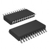
PCA9555DWR
Manufacturer
Texas Instruments
Introduction
I2C and SMBus-compatible interface expander with 16 I/O pins
Product Features and Performance
16 I/O pins expandable via I2C bus
Interrupt output for input change notification
Configurable polarity inversion register
Power-on reset (POR)
Product Advantages
Conserves microcontroller I/Os for other functions
Allows for serial interface to parallel expansion
Supports hot insertion
Key Technical Parameters
Number of I/O: 16
Interface: I2C, SMBus
Interrupt Output: Yes
Output Type: Push-Pull
Current - Output Source/Sink: 10mA, 25mA
Clock Frequency: 400 kHz
Voltage - Supply: 2.3V ~ 5.5V
Operating Temperature: -40°C ~ 85°C
Quality and Safety Features
Over-voltage tolerant inputs
Low standby current
Noise filter on SCL/SDA inputs
Compatibility
Interfacing with microcontrollers and processors that utilize I2C or SMBus
Application Areas
Keyboard extensions for microcontrollers
LED indicators and displays
Industrial control systems
Server management
Product Lifecycle
Active product status
No reported discontinuation or obsolescence
Several Key Reasons to Choose This Product
Flexible usage across wide voltage range (2.3V to 5.5V)
High I/O pin count ideal for complex systems
Robust design suitable for industrial applications
Compatible with popular communication protocols
Easy to mount with surface-mount technology
Efficient power management with low standby current
Enables sophisticated system monitoring with interrupt output feature


 PCA9555PWTexas InstrumentsIC XPND 400KHZ I2C SMBUS 24TSSOP
 PCA9555DBQRTexas InstrumentsIC XPNDR 400KHZ I2C SMBUS 24SSOP
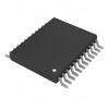 PCA9555DGVRTexas InstrumentsIC XPND 400KHZ I2C SMBUS 24TVSOP
 PCA9555N,112NXP USA Inc.IC XPNDR 400KHZ I2C SMBUS 24DIP
 PCA9555HF,118NXP USA Inc.IC XPND 400KHZ I2C SMBUS 24HWQFN
 PCA9555DB,118NXP Semiconductors
 PCA9555PW-TLUMILEDS


