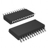

PCA9555DW (1)
Manufacturer Part Number
PCA9555DW
Manufacturer
Texas Instruments
Introduction
The PCA9555DW is an I/O expander for the I2C bus and SMBus, providing 16 additional I/O pins.
Product Features and Performance
16 I/O ports
I2C and SMBus interface
Interrupt output with POR feature
Push-Pull output type
Source/Sink current capability of 10mA and 25mA
Product Advantages
Extended I/O capability for processors with limited I/O pins
Flexible interface accommodating both I2C and SMBus
Built-in Power-on reset improves reliability on power-up
Support for both push-pull and open-drain configurations
Key Technical Parameters
Number of I/O: 16
Interface: I2C, SMBus
Interrupt Output: Yes
Features: Power-on Reset (POR)
Output Type: Push-Pull
Current - Output Source/Sink: 10mA, 25mA
Clock Frequency: 400 kHz
Voltage - Supply: 2.3V to 5.5V
Operating Temperature: -40°C to 85°C
Mounting Type: Surface Mount
Package / Case: 24-SOIC
Quality and Safety Features
Operational across a wide temperature range
Supports hot insertion
Compatibility
Compatible with various microcontrollers and processors with I2C or SMBus interface
Application Areas
Embedded systems
Industrial control
Home automation
Server motherboards
Product Lifecycle
Obsolete status indicates it's nearing discontinuation
Alternatives or upgrades should be considered
Several Key Reasons to Choose This Product
Expands I/O port availability in space-constrained applications
Supports industry-standard I2C and SMBus for easy integration
Provides design flexibility with various output types
Facilitates reliable system operation with built-in POR
Wide operating voltage and temperature range suitable for harsh environments
Compatibility with multiple devices and applications
Accommodates future needs with alternatives due to obsolescence
Offers ease of mounting with surface mount packaging technology

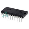 PCA9555N,112NXP USA Inc.IC XPNDR 400KHZ I2C SMBUS 24DIP
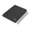
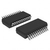 PCA9555DB,112NXP USA Inc.IC XPNDR 400KHZ I2C SMBUS 24SSOP
 PCA9555DBTexas InstrumentsIC XPNDR 400KHZ I2C SMBUS 24SSOP
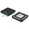 PCA9555HF,118NXP USA Inc.IC XPND 400KHZ I2C SMBUS 24HWQFN
 PCA9555PWTexas InstrumentsIC XPND 400KHZ I2C SMBUS 24TSSOP
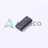 PCA9555DBQRTexas InstrumentsIC XPNDR 400KHZ I2C SMBUS 24SSOP
 PCA9555DBRG4Freescale / NXP Semiconductors


