

 PCA9555HF,118NXP USA Inc.IC XPND 400KHZ I2C SMBUS 24HWQFN
 PCA9555N,112NXP USA Inc.IC XPNDR 400KHZ I2C SMBUS 24DIP
 PCA9555PWTexas InstrumentsIC XPND 400KHZ I2C SMBUS 24TSSOP
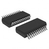 PCA9555DB,112NXP USA Inc.IC XPNDR 400KHZ I2C SMBUS 24SSOP
 PCA9555HFNXP Semiconductors
- Nath***rooks
- Jun 11, 2026
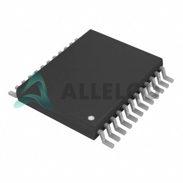
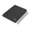
Image may be representation.
See specifications for product details.
See specifications for product details.
- EXPRESS OPTION
- Payment method
PCA9555DGVR - Texas Instruments
- Manufacturer Part Number
- PCA9555DGVR
- Manufacturer
- Texas Instruments
- Allelco Part Number
- 98D-PCA9555DGVR
- Warranty
- 1 Year Allelco Warranty - Find out more
- Stock Status:
- 49,628 pcs available, New & Original
- Parts Description
- IC XPND 400KHZ I2C SMBUS 24TVSOP
- Package
- 24-TVSOP
- Data sheet
-
PCA9555DGVR.pdf
HTML Datasheet
PCA9555.pdf
- RoHs Status
- ROHS3 Compliant
- Our certification
- In stock: 49628
- Unit Price: $2.848
- Subtotal: $0.00
Want a better price?
Add to Cart and Submit RFQ now, we'll contact you immediately.
| Quantity | Unit Price | Ext. Price |
|---|---|---|
| 1+ | $2.848 | $2.85 |
| 200+ | $1.102 | $220.40 |
| 500+ | $1.064 | $532.00 |
| 1000+ | $1.045 | $1,045.00 |
The above prices does not include taxes and freight rates, which will be calculated on the order pages.


