PCA9555DBQR (1)
Manufacturer Part Number
PCA9555DBQR
Manufacturer
Texas Instruments
Introduction
PCA9555DBQR is an integrated circuit for interfacing applications requiring additional I/O lines.
Product Features and Performance
16-bit I/O expander
I2C and SMBus compatible interface
Built-in interrupt output signaling feature
Power-on reset function
Push-pull output style
Supports 400 kHz I2C bus clock frequency
Product Advantages
Expands I/O capabilities for microcontroller based systems
Provides direct interface with most microprocessors
Reduces complexity by offering integrated features
Easy to use and integrate into existing designs
PCA9555DBQR (2)
Key Technical Parameters
Number of I/O: 16
Interface: I2C, SMBus
Interrupt Output: Yes
Features: Power-on reset (POR)
Current - Output Source/Sink: 10mA, 25mA
Clock Frequency: 400 kHz
Voltage - Supply: 2.3V to 5.5V
Operating Temperature: -40°C to 85°C
Quality and Safety Features
Robust operating temperature range for industrial applications
Complies with safety and regulatory standards
Proven reliability from Texas Instruments
Compatibility
Compatible with microcontrollers and processors supporting I2C or SMBus
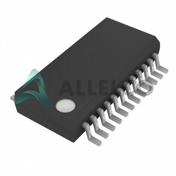
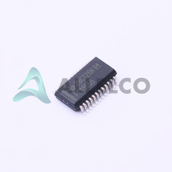
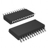
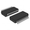
Suitable for breadboards and prototyping with 24-SSOP package format
Application Areas
Embedded systems
Industrial controls
Server management
Robotics
Home automation systems
Product Lifecycle
Last Time Buy status
Potential replacements or upgrades may be available
Several Key Reasons to Choose This Product
Industry-leading performance and reliability by Texas Instruments
Significant expansion of I/O lines for complex systems
Ease of integration into existing and new designs
Multi-voltage operations suitable for various applications
Strong support and documentation available from Texas Instruments


 PCA9555DB,112NXP USA Inc.IC XPNDR 400KHZ I2C SMBUS 24SSOP
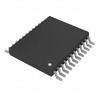 PCA9555DGVRTexas InstrumentsIC XPND 400KHZ I2C SMBUS 24TVSOP
 PCA9555BSHPNXP USA Inc.IC XPND 400KHZ I2C SMBUS 24HVQFN
 PCA9555HFNXP Semiconductors


