
INA159AIDGKR (1)
Manufacturer Part Number
INA159AIDGKR
Manufacturer
Texas Instruments
Introduction
High-precision, low-power instrumentation amplifier with rail-to-rail input/output
Product Features and Performance
Precision instrumentation amplifier with rail-to-rail input and output
Low noise and drift
Low power consumption
Wide common-mode and differential input voltage range
High input impedance
High CMRR and PSRR
Low offset voltage and bias current
Stable performance over temperature
Product Advantages
Ideal for medical, industrial, and data acquisition applications
Suitable for battery-powered and portable devices
Provides high-precision signal conditioning
Excellent for amplifying small differential signals
Key Technical Parameters
Operating voltage: 1.8V to 5.5V
Supply current: 1.1mA
Slew rate: 15V/s
Input offset voltage: 100μV
Amplifier type: Differential
-3dB bandwidth: 1.5MHz
Output current: 60mA
Quality and Safety Features
RoHS3 compliant
8-VSSOP package
Compatibility
Surface mount package
Wide operating temperature range: -40°C to 125°C
Application Areas
Medical instrumentation
Industrial process control
Data acquisition systems
Battery-powered portable devices
Product Lifecycle
Current product with no plans for discontinuation
Replacements and upgrades available if needed
Key Reasons to Choose This Product
High precision and accuracy
Low power consumption
Wide operating voltage and temperature range
Excellent common-mode rejection and power supply rejection
Suitable for a variety of instrumentation and data acquisition applications
Stable and reliable performance


 INA157UTexas InstrumentsIC OPAMP DIFF 1 CIRCUIT 8SOIC
 INA1620RTWTTexas InstrumentsIC AUDIO 2 CIRCUIT 24WQFN
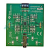 INA1620EVMTexas InstrumentsEVAL MODULE
 INA1620RTWRTexas Instruments
 INA157UKBURR-BROWN


