

TMDS181IRGZR (1)
Manufacturer Part Number
TMDS181IRGZR
Manufacturer
Texas Instruments
Introduction
The TMDS181IRGZR is an integrated circuit (IC) designed for specialized interface applications.
Product Features and Performance
High-performance TMDS retimer
Supports data rates up to 6 Gbps
Low power consumption
Adaptive equalization and re-clocking
Integrated cable drivers and receivers
Integrated cable equalizer
Supports HDMI, DVI, and DisplayPort interfaces
Product Advantages
Enables long-distance high-speed signal transmission
Enhances signal integrity and reliability
Simplifies design and reduces system complexity
Optimizes power efficiency
Key Technical Parameters
Supply voltage: 1.2V, 3.3V
Data rate: Up to 6 Gbps
Packaging: 48-VQFN (7x7)
Quality and Safety Features
RoHS3 compliant
Designed for reliable and durable performance
Compatibility
Compatible with HDMI, DVI, and DisplayPort interfaces
Application Areas
Retimer applications in high-speed digital video systems
Long-distance signal transmission in display, computing, and imaging systems
Product Lifecycle
The TMDS181IRGZR is an active and widely available product from Texas Instruments.
Key Reasons to Choose This Product
High-performance TMDS retimer with advanced signal processing capabilities
Supports high data rates up to 6 Gbps
Optimizes power efficiency and simplifies system design
Ensures reliable and durable performance with RoHS3 compliance
Compatibility with a wide range of high-speed digital video interfaces


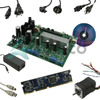 TMDS1MTRPFCKITTexas InstrumentsKIT DEV F28035 MOTOR CTRL/PFC
 TMDS171RGZTTexas Instruments
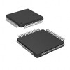 TMDS250PAGRTexas InstrumentsIC VIDEO SWITCH 64TQFP
 TMDS243EVMTexas InstrumentsAM243X EVALUATION MODULE FOR ARM
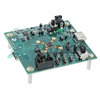 TMDS171RGZEVMTexas InstrumentsEVAL BOARD FOR TMDS171
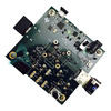 TMDS181RGZEVMTexas InstrumentsEVALUATION MODULE
 TMDS141RHARG4Texas InstrumentsIC INTERFACE SPECIALIZED 40VQFN
 TMDS141RHARTexas InstrumentsIC INTERFACE SPECIALIZED 40VQFN
 TMDS251PAGTexas Instruments
 TMDS141RAAR


