

TMUX1119DBVR (1)
Manufacturer Part Number
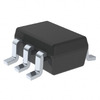
TMUX1119DBVR
Manufacturer
Texas Instruments
Introduction
High-performance SPDT switch optimized for low-voltage operation
Product Features and Performance
Single Pole Double Throw (SPDT) configuration
2:1 Multiplexer/Demultiplexer functionality
Low on-state resistance of 4 ohms max
Excellent channel-to-channel matching of 130 milliohms
Wide supply voltage range from 1.08V to 5.5V
Large -3dB bandwidth of 250MHz
Negligible charge injection of -6 picocoulombs
Low channel capacitance of 6 picofarads (off-state)
Minimal current leakage at 80 picoamperes (max in off-state)
Reduced crosstalk at -45dB at 10MHz
Operating temperature range from -40°C to 125°C
Product Advantages
Suited for high-speed and precision applications
Supports a broad range of supply voltages
Minimal signal distortion
Robust performance across temperature ranges
High signal integrity with low crosstalk
Energy-efficient with low power consumption
Key Technical Parameters
SPDT switch circuit
1 circuit per chip
On-State Resistance: 4Ohm max
Voltage Supply Range: 1.08V to 5.5V
Operating Temperature: -40°C to 125°C
Bandwidth: 250MHz
Quality and Safety Features
Ensuring stable operation through harsh temperatures
Designed according to industry safety standards
Compatibility
Compatible with various electronic systems due to a wide supply voltage range
SOT-23-6 package fits standard surface mount processes
Application Areas
Telecommunications
Data acquisition systems
Test equipment
Audio/Video signal routing
Medical devices
Portable electronics
Product Lifecycle
Currently active product
Not reported as nearing discontinuation
Texas Instruments provides support and potential future upgrades
Several Key Reasons to Choose This Product
Offers high-bandwidth capability suitable for fast-switching applications
Low power consumption conducive to battery-operated devices
Texas Instruments' reputation for reliability and performance
Flexible operation across a wide voltage range and temperatures
State-of-the-art package design for ease of integration into existing systems
 TMUX1109PWRTexas InstrumentsIC MUX DUAL 4:1 4OHM 16TSSOP
 TMUX1134PWRTexas InstrumentsIC SWITCH SPDT X 4 4OHM 20TSSOP
 TMUX1136DGSRTexas InstrumentsIC SWITCH SPDT X 2 4OHM 10VSSOP
 TMUX1112PWRTexas InstrumentsIC SWITCH SPST X 4 4OHM 16TSSOP
 TMUX1136DQARTexas InstrumentsIC SWITCH SPDT X 2 4OHM 10USON
 TMUX1123DGKRTexas InstrumentsIC SWITCH SPST X 2 4OHM 8VSSOP
 TMUX1111PWRTexas InstrumentsIC SWITCH SPST X 4 4OHM 16TSSOP
 TMUX1204DGSRTexas InstrumentsIC SWITCH SP4T X 1 5OHM 10VSSOP
 TMUX1122DGKRTexas Instruments


